Construction
The project delivery method is a type of design-bid-build, with preconstruction services added. Forrester Construction Company offered paid preconstruction services, but was selected based on a competitive bid since it is a public project. Forrester’s contract as a GC is a negotiated guaranteed maximum price. Due to the short schedule, this agreement allowed for allowances for aspects of the design that were not 100% complete when the contract was signed. The general contracting services are offered as a joint venture between Forrester Construction and Columbia Enterprises.
Before construction could begin, demolition had to occur. Approximately 150,000 SF of demolition was required to build the new Walker Jones School. Terrell Junior High School was demolished to allow room for construction and the adjacent Walker Jones Elementary School will be completely demolished once the new school is complete. The majority of the demolition was concrete and masonry which was crushed onsite. This material was then used as backfill in several areas to save money.
Several issues required an abatement crew to prepare the school prior to being wrecked. There was a small amount of asbestos used in Terrell Junior High. In addition, the fluorescent light fixtures had to be removed because of the hazardous materials contained in the older ballasts. Below the structure there were also two abandoned fuel tanks, 10,000 and 20,000 gallons which needed to be dealt with. The smaller tank was not a problem to remove; however, the larger tank was leaking. Due to schedule impacts, the larger tank was covered and removed at a later time. Special precautions had to be taken around the tank- the soil needed to be separated, removed, and treated properly. During demolition on the west side of the site, excavation work began on the portion of the site where the new school is located.
Lighting/Electrical
The main service feeder for the building enters from Pepco transformer vaults in the North-East corner of the building adjacent to the basement mechanical room. The service is 3 Phase, 4 Wire, 480/277 Volt with a 3000A Main Switchboard. Emergency power is supplied by a 275kW 480/277V generator with a 500 gallon fuel tank for 23 hours of operation at full load. The generator is located outside the building adjacent to the Pepco ductbank in a sound attenuated enclosure. All classrooms and labs are equipped with occupancy sensors to ensure lights are only on when the room is occupied.
Mechanical
The heating, ventilating and air conditioning system provides the facility with equipment that meets the long term energy efficiency and maintenance priorities as well as being a cost effective solution. The system provides flexibility and increased energy savings opportunities. Each air handling unit (AHU) zone is capable of an independent operating schedule. Each of the eight air handling units is responsible for an individual zone. Zones 1-8 are broken into east, west, north and south classroom blocks, cafeteria, library, gymnasium, and kitchen, respectively.
The mechanical rooms are located in Area C in a partial basement and on the third floor above the kitchen. The building’s eight air handling units are located on the roof of the building. Each air handling unit will be provided with a DX cooling coil, hot water heating coil, 30% and 85% efficient filters as well as access sections for maintenance to all coils and filters. All fans will be provided with variable frequency drives (VFD’s) and energy recovery wheels will be provided for AHU’s 1, 2, 3, 4 and 7 to maximize energy efficiency.
The cafeteria, gymnasium and kitchen have constant air volume systems while the rest of the building has a variable air volume (VAV) system. Heating water will be generated from three (3) gas fired boilers located in the northeast mechanical room above the kitchen. Two (2) heating water pumps (primary and standby) will circulate heating water to the air handling units.
Controls
Automatic temperature controls are web-based, electrically actuated, direct digital control (DDC). The entire temperature control system as well as all associated control components and mechanical equipment (chiller, boilers, VFD’s, etc.) are Bacnet compatible.
Each classroom is provided with a separate air terminal (VAV) to provide independent room temperature control. Offices where usage and exposure are similar are combined on common VAV terminals.
All major mechanical equipment items (chilled and heating water source equipment, air handling units, pumps, etc.), as well as all air terminals, temperature sensors, etc., will be capable of being controlled and/or monitored through the web-based energy management control system (EMCS).
Structural
Structurally, the building is divided into three sections, as shown in Figure 2. SECTION 1 consists of the 4 STORY K-8 CLASSROOMS, 3 STORY K-8 CLASSROOMS, the PUBLIC LIBRARY, and the 2 STORY LOCKERS/ MULTI-PURPOSE. SECTION 2 is the CAFETERIA/ KITCHEN WITH PARTIAL MECH BASEMENT. SECTION 3 is the GYMNASIUM.
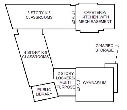
Figure 2. Structural Sections of the Building
SECTION 1:
The 4 STORY K-8 CLASSROOMS, the PUBLIC LIBRARY, and the 2 STORY LOCKERS/ MULTI-PURPOSE are founded a story below the 3 STORY K-8 CLASSROOMS portion of SECTION 1 as grading drops an entire story across the site. The 3 STORY K-8 CLASSROOMS and the 4 STORY K-8 CLASSROOMS share the same roof. Typical floor to floor height is 14’.
Foundations and Slab on Grade:
The lower floor consists of 5” concrete (3500 psi) slab on grade reinforced with 6”x6” W.21/W2.1 welded wire reinforcing over vapor barrier over 12” granular fill and an under-slab drainage system.
The foundation system is spread footings which bear on ground reinforced with impact piers, providing an allowable bearing strength of 6000 psf. The north, west, and south exterior walls of the structure are against the property line. The footings of these walls and the footings of columns along the perimeter at these walls may not cross the property line. For this reason, interior grade beams are utilized to accommodate the eccentric load.
The typical foundation walls are reinforced concrete (concrete masonry units). Approximately 700’ feet of the foundation walls at the four story wing will be either fully or partially retaining earth. The walls which are retaining earth are 15” cast in place 4000 psi concrete.
Floor Framing:
The structural floor is a 5 ½” slab (3 ½” of lightweight 4000 psi concrete topping over 2” x 18 gauge composite metal deck) supported by wide flange steel beams (composite beams with ¾” diameter x 4” headed studs at 12” on center) at 8’-0” on center. The beams are supported by wide flange steel girders (composite beams with two ¾” diameter x 4” headed studs at 12” on center) along the perimeter and along either side of the corridor running the length of the classroom wings. The girders and beams are supported by wide flange steel columns. The columns are positioned at the perimeter and on either side of the corridor and spaced approximately 24’ on center.
Roof Framing:
The typical structural roof supporting the green roof is a 5 ½” slab (3 ½” of light weight psi concrete topping over 2” x 18 gauge composite metal deck). The slab is supported by wide flange steel beams (composite beams with ¾” diameter x 4” headed studs at 12” on center) at 8’-0” on center. The roof is sloped ¼” per foot to interior drains.
Exterior Walls:
The brick exterior walls are backed up with 6” light gage metal stud. Typical window openings on the exterior wall are “punch” windows and loose angle lintels are provided to span the openings, in addition brick veneer are hung from the floor above with galvanized steel “shelf” angles.
Lateral Force Resisting System:
Steel moment frames and reinforced CMU shear walls resist wind and seismic lateral forces.
SECTION 2:
The CAFETERIA/ KITCHEN WITH PARTIAL MECH BASEMENT is located at the east end of the three story classroom wing. The roof of the cafeteria/ kitchen is approximately 30’ above finished grade.
Foundation and Slab on Grade:
Same as SECTION 1 with the exception of the mechanical basement. The mechanical basement floor is 6” 3500 psi concrete slab on grade.
Floor Framing:
The structural floor over the mechanical basement is a 5 ½” slab (3 ½” of lightweight 4000 psi concrete topping over 2” x 18 gauge composite metal deck) supported by wide flange steel beams (composite beams with ¾” diameter x 4” headed studs at 12” on center) at 8’-0” on center.
Roof Framing:
The roof framing is 1-1/2” x 22 gauge metal deck in 3 spans supported by steel bar joists spaced from 4’-0” to 6’‑0” on center, specially designed to accommodate equipment hung from the roof spanning between CMU bearing walls.
Exterior Walls:
The exterior walls are reinforced CMU bearing walls clad with a brick veneer separated by an air space cavity. The perimeter walls of the basement are 12” poured in place concrete. The areaway retaining walls and basement walls retaining earth are poured in place concrete.
Lateral Force Resisting System:
The perimeter CMU bearing walls resist wind and seismic lateral forces.
SECTION 3:
The one story GYM/ REC STORAGE is located on the east side of the GYMNASIUM. The roof of the gymnasium is 34’ above finished grade. The roof of the storage rooms is 13’ above finished grade.
Foundations and Slab on Grade:
Same as SECTION 1 with the exception of the footings on the south wall. This wall is constructed against the property line so the footings will be increased in size to accommodate the eccentric load.
Roof Framing:
Same as SECTION 2.
Exterior Walls:
The exterior walls are reinforced CMU bearing walls clad with a brick veneer separated by an air space cavity. Earth retaining walls on the North side of the gymnasium are 12” poured in place concrete, with reinforced CMU bearing walls above grade.
Lateral Force Resisting System:
The perimeter CMU bearing walls resist wind and seismic lateral forces.
Fire Protection
The building is provided with a wet pipe fire protection sprinkler system in accordance with NFPA and the local authority. Standpipe risers are provided in each stairwell and sprinkler zone assemblies are provided (minimum one per floor) to provide sprinkler coverage throughout the facility. A fire pump is provided to meet the fire protection system flow and pressure required by the local authority.
Plumbing
Separate incoming water services are extended from Pierce St to a 4-inch domestic water and an 8-inch fire protection service to the building. In addition, the building is connected to an existing 20 psi gas main located in Pierce St located to the north of the building. A domestic water booster pump is provided to meet the pressure requirements of the fixtures within the building. Domestic hot water is generated from a gas-fired water heater located in the northeast mechanical room above the warming kitchen. Hot water distribution temperature is set for 140ºF to the warming kitchen and 110ºF for all other areas.